How to Choose Passive Components in 2026?
In 2026, choosing passive components means looking beyond a single value. A capacitor marked 10 µF, for example, may provide less effective capacitance under DC bias. A resistor can drift as temperature rises, while an inductor may saturate during a brief current spike. Small details matter. These effects can influence noise, heat, startup behavior, and product life. The right choice depends on the circuit, its operating range, available board space, and the conditions the finished device will face.
This guide explains how to compare capacitors, resistors, and inductors using practical design criteria. It covers tolerance, voltage and current ratings, frequency response, temperature limits, package size, and derating. It also considers availability and datasheet quality, because a technically suitable part is not useful if its specifications are unclear or supply is uncertain. Check key assumptions against the manufacturer’s documentation, then validate critical choices in the actual circuit. A bench test may reveal behavior that a tidy spreadsheet misses. That is not a failure of the process; it is a reminder that models have limits. Component selection involves trade-offs, and the lowest price or smallest footprint is not always the safest long-term choice. The aim is a defensible fit for the application, not a perfect part on paper.
Identify the Passive Component Types and Their Roles
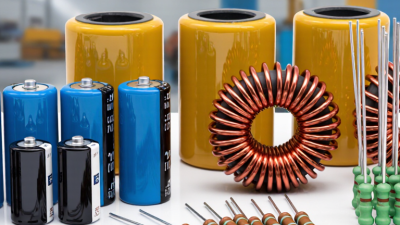
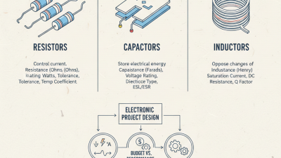
Passive components do not amplify a signal, but they strongly influence how reliably a circuit behaves. A resistor limits current, divides voltage, or sets a sensor’s operating point. On a compact board, it can also generate heat, so check its power rating as well as its resistance. Capacitors store charge and smooth voltage changes. Near a processor, small capacitors can help manage fast electrical noise, while larger ones often support slower load changes. That distinction matters.
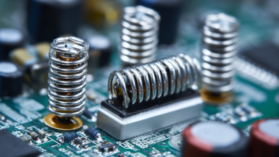
Inductors store energy in magnetic fields and resist sudden changes in current. They are common in power converters and filters. Ferrite beads can help reduce high-frequency interference, but they are not interchangeable with inductors. Thermistors change resistance as temperature shifts, making them useful for sensing or limiting startup current. Varistors can limit brief voltage surges, though repeated stress may degrade their protection. The categories overlap in real circuits, which can make a quick parts list misleading.
For a 2026 design, start by identifying the job each component must perform. Then compare operating voltage, current, tolerance, temperature range, and power or ripple ratings in the datasheet. A capacitor that fits physically may still be unsuitable under actual voltage and temperature conditions. Check the circuit at the bench, too: measure temperature and ripple after the board has run under load. I have seen a tidy schematic hide a warm resistor. That is a useful reminder, not a universal rule.
Define Electrical, Environmental, and Mechanical Requirements
Choosing passive components in 2026 starts with the circuit’s actual operating conditions, not just its nominal values.
Record working voltage, peak current, ripple, frequency, and allowable tolerance. A capacitor near its voltage limit may lose capacitance or age faster than expected. A resistor needs enough power margin to handle heat inside the real enclosure. Small margins matter. Check the datasheet’s test conditions, too; a quoted value can shift with temperature or frequency.
Environmental requirements deserve equal attention.
Define the minimum and maximum temperatures, humidity exposure, and likely vibration before comparing parts. A device beside a warm power stage faces different conditions from one in a climate-controlled cabinet. Consider moisture and repeated temperature changes, especially when the assembly is sealed. The first estimate is rarely the final one. Review it against measurements from a prototype, because airflow and nearby components can change local temperatures.
Mechanical fit can quietly undo a sound electrical choice.
Check body dimensions, lead spacing, mounting orientation, clearance, and board flex. A tall component may collide with a cover, while a heavy part can strain solder joints during vibration. Confirm that the selected footprint matches the package drawing, not just a library symbol. Fit is not trivial. I would also leave room for assembly variation; a design that works only with perfect placement may need another revision.
Compare Key Ratings, Tolerances, and Package Options
How to Choose Passive Components in 2026?
Selecting passive components means comparing real operating limits, not just matching nominal values. WSTS’s Fall 2024 forecast put global semiconductor sales at about $626 billion in 2024, reflecting continued demand for increasingly capable electronics. That growth makes heat, board space, and supply continuity practical design concerns. For resistors, check power rating and temperature coefficient; for capacitors, compare rated voltage, ripple current, ESR, and capacitance loss under DC bias. Inductors need adequate saturation and RMS current ratings. IEC 60115-1 and IEC 60384-1 provide standardized frameworks for resistor and capacitor specifications, but application conditions still matter.
Tolerance affects circuit accuracy and cost. A 1% resistor may suit a sensing path, while a wider tolerance can be adequate in a noncritical pull-up. For capacitors, tolerance alone does not show how much capacitance remains at operating voltage and temperature. Package size also changes heat dissipation, mounting strength, and assembly options. A smaller package saves board area, but may run hotter or be harder to inspect. The datasheet’s test conditions can differ from the actual circuit. That detail is easy to miss.
Tips: Compare ratings at your actual temperature and frequency. Leave margin for voltage spikes and current peaks. Check package dimensions against the footprint, then confirm availability across more than one supplier. A tidy spreadsheet helps, but it cannot replace a prototype test.
Verify Component Performance Through Testing and Simulation
When choosing passive components in 2026, treat datasheet values as a starting point, not a guarantee. A capacitor’s effective capacitance can fall under DC bias, while temperature and aging also shift its behavior. Check inductors for saturation current and winding resistance. For resistors, review tolerance, temperature coefficient, and pulse limits. Small differences matter. In a tightly regulated power rail, a few milliohms of extra resistance can change heat and voltage drop. Simulate realistic operating corners, including component tolerances and board parasitics, rather than relying on nominal values alone.
Tips: Build a short test plan before ordering. Measure samples at expected voltage, temperature, and load. Record the setup, instrument accuracy, and results. Keep the raw data. It helps later.
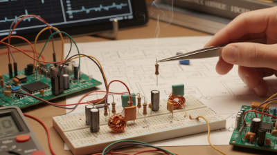
Simulation narrows the choices, but bench testing checks what the model misses. Compare predicted ripple, startup behavior, and component temperature with measurements from a representative board. Use suitable probes and avoid long ground leads, which can distort high-frequency readings. Test more than one sample when variation could affect performance. A model may look convincing and still be incomplete; that is worth admitting. If results disagree, review assumptions such as capacitor bias curves, inductor core losses, and layout parasitics. Update the model and repeat the test before approving the part.
How to Choose Passive Components in 2026: Verify Performance Through Testing and Simulation
Ceramic capacitor temperature classes provide a useful first screening step. The ranges shown are class limits: X7R and X5R allow up to ±15% capacitance change over their specified temperature ranges; C0G/NP0 is characterized by a temperature coefficient of ±30 ppm/°C.
Verification note: These class limits do not capture every in-circuit effect. Check the selected part’s datasheet, simulate capacitance under operating bias, and confirm performance with temperature-chamber and application-level testing.
Assess Availability, Compliance, and Long-Term Reliability
A passive component is only a sound choice if it can be sourced when production needs it. In 2026, compare current stock with quoted lead times, minimum order quantities, and the supplier’s history of allocation changes. A low price means little if delivery slips by twelve weeks. Ask for dated availability data and confirm whether the quoted part is an exact match or a proposed substitute. Check the date.
Compliance needs more than a checkbox on a product page. Review material declarations and confirm they apply to the exact part number and manufacturing site. Requirements can differ by market and product type, so verify current rules with qualified compliance staff. Keep declarations, revision records, and supplier correspondence together. That paper trail helps when a design changes or an audit raises questions.
Long-term reliability starts with the circuit conditions, not just a component’s headline rating. Check operating temperature, voltage, ripple current, tolerance, and expected service life. Leave sensible margin; a capacitor running near its temperature limit may age faster than the design team expects. Compare failure data where available, and ask how changes to materials or production are communicated. A spreadsheet can still miss a quiet revision. Recheck critical parts during design reviews, because yesterday’s dependable source may not remain available tomorrow.